Thursday 10 May 2018

MSc meets Micro:Bit

I have recently been teaching a module on Internet Programming on a MSc Computing programme (see related links), and was looking for a way to introduce a little bit of physical computing to finish of the module - micro:bits offer a route.

So a bit of context; most of the students on the module had first degrees in either networking or software engineering; so before they start the module they are competent in programming with Javascript, HTML, CSS and PHP. Therefore the module looked to develop new areas such as introductory blockchainvirtual reality via the web (e.g. WebVR), using social media sources; but lastly looking at physical computing leading to an insight into the Internet of Things (IoT). As part of this last topic gaining some experience of programming and very simple networking was looked at using the micro:bit.

An activity was produced where:

  • they, in pairs, initially replicate some code and work out how it worked;
  • they then took the code and experimented with their own ideas.
In all cases they had to produce something that allowed doing something on one micro:bit, caused another micro:bit to do something in response.


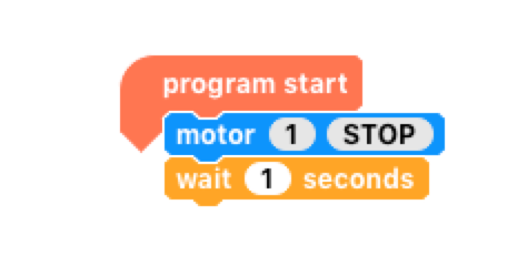
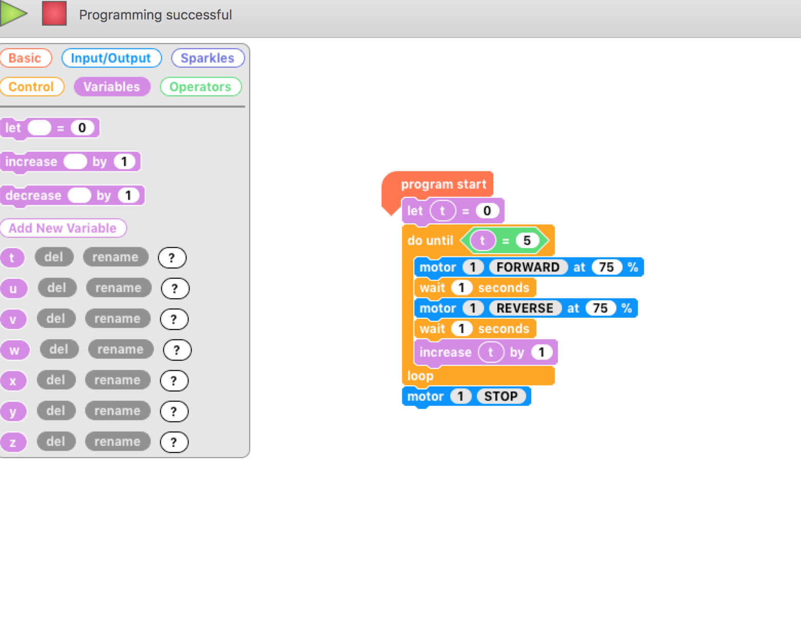
Initially, javascript blocks (as above) were used and some students stuck with the graphical blocks, others moved into the text-based version. As far as the activity went it didn't matter; the main goals were to see the programming of a physical device via a web interface; to break a little mystique that it is as ways much harder to program physical devices and to get a bit of very simple networking going on.

Many of the students, started to investigate getting sounds to play on headphones and getting one micro:bit to trigger the other to play. One group went and started playing with python. 

Reflection bit - If I had similar, competent group again I would start this earlier; the level of engagement seemed high and the activities could then start developing towards IoT. Though, I admit to a bias for physical computing, it is appropriate in HE teaching; even using tools primarily designed for schools like the micro:bit.


Related Links
MSc Computing
MSc Computing (Computer Network Engineering)
MSc Computing (Software Engineering)


All opinions in this blog are the Author's and should not in any way be seen as reflecting the views of any organisation the Author has any association with. Twitter @scottturneruon

Friday 20 April 2018

Summary of Robots at BCS Northampton

On the 17th April 2018 I had the honour of presenting a public talk on robots for the Northampton Branch of the Britsh Computer Society (BCS). This post aims to summarise the session.

The session was really from a personal perspective and journey, covering where I think robots in home and schools are going, and an overview of some of the projects I have been involved. First, part was the presentation - the slides are shown below.


The videos used in the presentations are shown below. The first video is an introduction and welcome from Red the Nao robot.


Next video shows a programmed Cozmo, using Anki's graphical programming language.


Second section of the session was playing with the robots. Red the Nao, an Anki Cozmo and an UBtech Alpha2 and having a play with a Crumble-based junkbots.  Crumble junkbots were used on PC and Raspberry Pi via Pi-top CEED.
Red (at the back), alpha 2 (middle) and Cozmo (front)

Crumble controller from Redfern Electronics

Crumble as part of a junkbot.

Highlights of the evening were Red going for a walk 'hand-in-hand' with one of the audience and Cozmo chatting away; as always (and rightly) the stars of the talk are the robots. 


All opinions in this blog are the Author's and should not in any way be seen as reflecting the views of any organisation the Author has any association with. Twitter @scottturneruon

Tuesday 3 April 2018

How to produce a Microbit neural network

This is really part two of a set of post in response to a question from Carl Simmons (@Activ8Thinking) concerning building a micro:bit simple neuron. In the previous post a single neuron was produced. This post looks at producing a network of neurons, ie. neural network; looking to solve the problem that a single neuron can't solve, making an Exclusive OR gate (XOR)


1. Quick Overview
1.1 The neuron itself

  • Inputs are going to be binary
  • Weighted sum is bias+W1*input1+w2*input2
  • If weighted sum>=0 then the output is True (T on the LEDs) or '1'
  • If weighted sum<0 then the output is False (F on the LEDs) or '0'
1.2 The XOR
Essentially for the two input case if the two inputs are different then the output is True.

The figure below shows the arrangement of the connections; pin 2 is the output of the neurons. The two micro:bits/neurons on the left of the picture taking in the two inputs, the same inputs go to these two neurons; the output from these neurons are the two inputs to the output neuron on the right.


figure 1


The micro:bit objects used in Figure 1 were produced using the micro:bit Frtzing diagram available at https://github.com/microbit-foundation/dev-docs/issues/36 thanks to David Whale (@whalleygeek ) for these.


2. Neuron 1
This is the top left neurone in figure 1. This neurone is set to produce an output of TRUE (pin 2 going high) when the first input goes low and the second input goes high. The code for it is shown below.


3. Neuron 2
This is the bottom left neuron in figure 1. This neurone is set to produce an output of TRUE (pin 2 going high) when the first input goes high and the second input goes low. The code for it is shown below.


4. Output Neuron
Neuron 1
This is the right-hand neurone in figure 1. This neurone is set to produce an output of TRUE (pin 2 going high) when either inputs (outputs from neurons 1 and 2) goes high - in other words acting as an OR gate . The code for it is shown below. 

The overall effect is when the two inputs to the network are high/TRUE then the output of the network (this neuron) is TRUE.


5. In Action
The wiring is messy but the effect is possible to see in these images. The top neuron is the output neuron.
figure 2: inputs to the network (input 1 low and input 2 high)
Figure 3: inputs to the network (input 1 high and input 2 low)

figure 4: inputs to the network (both inputs the same)
6. Room for expansion
The neurons were 'trained' in this case by selecting the weights by hand, an improvement would be to get them to learn. How to do this on a micro:bit takes a bit more thinking about, but I would be interested in seeing how others solve that problem.


All opinions in this blog are the Author's and should not in any way be seen as reflecting the views of any organisation the Author has any association with. Twitter @scottturneruon

Friday 2 March 2018

Microbit Neuron - producing a single neuron using a microbit

This post is in response to a question from Carl Simmons (@Activ8Thinking) about has anyone built a microbit simple neuron.


Quick Overview

  • Inputs are going to be binary
  • Weighted sum is bias+W1*input1+w2*input2
  • If weighted sum>=0 then the output is True (T on the LEDs) or '1'
  • If weighted sum<0 then the output is False (F on the LEDs) or '0'


First attempt - A simple gate using the buttons A and B
So first attempt uses the A and B buttons on the Microbit as the two inputs and it produces T for true and F for false on the LEDs. So the weights produce an AND if the bias is changed from -2 to -1 you get an OR.


More Physical Solution for Single Neuron

So in this case the buttons are removed and P0 and P1 formed the inputs the weights are the same as in the previous example with the bias of -2 being used to produce a AND gate. Programming-wise this is a simpler solution than the previous one, no converting button presses into inputs.


Figures below show the 'neuron' in action.

First, one shows the case when both inputs are '0' ie. not connected to 3v connection. The output is False (F on the LEDs)


This figure shows when only one input is '1', the output is False.


Finally what happens when both inputs are '1', the output goes to True (T on the LEDs).


Where next?
Adapting the code so it produces a digital output and then combining them into a small network to solve a problem that a single neuron can't do the Exclusive OR (XOR).


All opinions in this blog are the Author's and should not in any way be seen as reflecting the views of any organisation the Author has any association with. Twitter @scottturneruon

Tuesday 27 February 2018

WebVR playtime 2: video, 360 video and objects

This is going to be a short series of articles about some experiments with WebVR Web based Virtual Reality - in this case based on the wonderful A-Frame (https://aframe.io) . In the first post WebVR playtime 1: Basics of setting up, images and rotating blocksI looked at setting up a scene and then rotating an object.

In this post, I going to recap the basics, then look at adding video, 360 degree video, and models developed elsewhere.


1. The approach and setting up

I chose to use A-Frame (https://aframe.io) inside Thimble (https://thimble.mozilla.org ); Thimble was selected for four reasons it is an online editor,  simple to use, it is free and you see the preview immediately. In Thimble though try to keep the image or video file sizes small.

You can pretty much treat it as HTML, after you have added the script file shown in bold.
<!DOCTYPE html>
<html>
  <head>
    <meta charset="utf-8">
    <meta name="viewport" content="width=device-width, initial-scale=1">
    <script src="https://aframe.io/releases/0.7.0/aframe.min.js"></script>
  </head>
  <body>
    <a-scene>

    </a-scene>
  </body>

</html>
The items to be add all go between <a-scene> and </a-scene>:
      <a-text value="Hello" color="black" position="0 1.8 0.5" width="10"></a-text>
      <a-sky color="orange" ></a-sky>
For example
    <a-scene>
      <a-text value="Hello" color="black" position="0 1.8 0.5" width="10"></a-text>
      <a-sky color="orange" ></a-sky>
    </a-scene>

The video below shows setting up and adding a box to the scene.


2. Adding video
Actual in some ways it as easy to add video as adding an image, at it's simplest adding src="" with either the URL or relative filename in the speech marks can be used for both images and video. Alternatively using <a-video src=""></a-video> combination with again the filename or URL between speech marks adds a block and pastes the video on top. The video below shows a worked example of these two approaches


3. 360 degree video.
A-Frame allows 360 degree to be incorporated into the scene using the <a-videosphere> tag. The video below shows a worked example of this. The video below shows another worked example.


4. 3D objects and Assets
We can also add 3D models that others have developed into our scene. In the video below a Penguin, defined externally using .obj for the model and .mtl for the material, is loaded into the scene.


To read more go to https://aframe.io/docs/0.7.0/introduction/ 


All opinions in this blog are the Author's and should not in any way be seen as reflecting the views of any organisation the Author has any association with. Twitter @scottturneruon

Sunday 25 February 2018

WebVR playtime 1: Basics of setting up, images and rotating blocks.

This is going to be a short series of articles about some experiments with WebVR Web based Virtual Reality - in this case based on the wonderful A-Frame (https://aframe.io) . Ok, a bit of context, I have been working with some MSc students on this area and we have been exploring this area together - I love learning from and with my students.

Firstly, it is great fun and nowhere near as hard as I thought it was going to be when I first started. 

1. The approach
My approach is to use A-Frame (https://aframe.io) inside Thimble (https://thimble.mozilla.org ). Thimble was selected for four reasons it is an online editor,  simple to use, it is free and you see the preview immediately. Its main downside is the size of images and videos has to be relatively small and not too many of them.

2. How easy is it?
You can pretty much treat it as HTML, after you have added the script file shown in bold.
<!DOCTYPE html>
<html>
  <head>
    <meta charset="utf-8">
    <meta name="viewport" content="width=device-width, initial-scale=1">
    <script src="https://aframe.io/releases/0.7.0/aframe.min.js"></script>
  </head>
  <body>
    <a-scene>

    </a-scene>
  </body>

</html>
The items to be add all go between <a-scene> and </a-scene> with a parent-child relationship; for example A block of text saying Hello in black and making the sky orange are all 'children' of <a-sceme>:
      <a-text value="Hello" color="black" position="0 1.8 0.5" width="10"></a-text>
      <a-sky color="orange" ></a-sky>
For example
    <a-scene>
      <a-text value="Hello" color="black" position="0 1.8 0.5" width="10"></a-text>
      <a-sky color="orange" ></a-sky>
    </a-scene>

The video below shows setting up and adding a box to the scene.


This next video takes this a little further by adding rotation to an object.


In this video mapping an image to an object and changing camera position is looked at.


In later posts some further ideas will be explored. 

To read more go to https://aframe.io/docs/0.7.0/introduction/ 


All opinions in this blog are the Author's and should not in any way be seen as reflecting the views of any organisation the Author has any association with. Twitter @scottturneruon

Monday 25 December 2017

Gesture controlled python robot unicorn (or is it a rhino)

In the previous two post I built and played with a robot unicorn from Do it Kitshttps://doitkits.com/product/robot-unicorn/. In the first post, python was used to get it to move forward, backwards, left, right and stop. The second post discussed using a second microbit to send the movement instructions via the microbit's  radio module.


This post looks at extending the idea to using the accelerometer to pick up directions and send them to the robot unicorn (that still seems weird to write). Microbit's accelerometers, using the x and y directions, provide the inputs and then send the direction commands. The robot unicorn code is the same in the second post, the new code for the gestures is shown below. 


This a work in progress it detects x and y changes together so it does have a tendency to do one direction and then the other. This needs further work.

All my code for the robot unicorn projects can be found at: https://github.com/scottturneruon/Robo_unicorn_python or if you want to cite it : Turner, S., 2017. Robo_unicorn_python. Available at: <Robo_unicorn_python> https://doi.org/10.6084/m9.figshare.5729583.v7

All opinions in this blog are the Author's and should not in any way be seen as reflecting the views of any organisation the Author has any association with. Twitter @scottturneruon

Saturday 23 December 2017

Radio controlled microbit Robot Unicorn

In a previous post a robot unicorn was built from a kit (Do it Kits https://doitkits.com/product/robot-unicorn/) and controlled to do a fixed sequence of actions. In this post a similar thing will be done, but this time the actions are not fixed within the robot itself, but in response to messages sent from another microbit via the radio module.


Sending


Sends out messages via the microbit's radio module, e.g. fwd for forward or tr for turn right; as well the name of the actions scrolls across the microbit.


On the Unicorn


Revieves messages via the microbits radio module, e.g. bwd for backward or tl for turn left; then carries out the action for 500ms. The time was selected to give the system enough time to finish the action before the next message is expected.


All the code available at Turner, S., 2017. Robo_unicorn_python. Available at: <Robo_unicorn_python> https://doi.org/10.6084/m9.figshare.5729583.v7

All opinions in this blog are the Author's and should not in any way be seen as reflecting the views of any organisation the Author has any association with. Twitter @scottturneruon

Friday 22 December 2017

Robot Unicorn, python and a microbit

Yesterday (21/12/2017) I took delivery of a Robot Unicorn kit - now those were three words I don't think I would ever write let alone say from Do it Kits https://doitkits.com/product/robot-unicorn/ based around the microbit.

There is a fantastic video produced by Do It Kits on how to put the kit together and another on programming using Blocks:


Using the second video as a starting point I have produced my version of it in Python (see below). Essentially go forward, backwards, turn left and turn right, as well as pause.

I have probably wired it up back to front, so my settings in the code are the other way around to the ones used in the video - you may need to swap backwards and forwards around; as well as left and right.


This is a cute kit. How can anyone resist a Robot Unicorn?

All of the code available at Turner, S., 2017. Robo_unicorn_python. Available at: <Robo_unicorn_python> https://doi.org/10.6084/m9.figshare.5729583.v7

All opinions in this blog are the Author's and should not in any way be seen as reflecting the views of any organisation the Author has any association with. Twitter @scottturneruon

Sunday 19 November 2017

Micro:bit Robot Arm

In this post, I am discussing using a recently bought  CBIS BBC micro:bit RobotArm, but play with it using Python (or rather micropython).


Set Up
Not a lot to set up really. The base and the arm are separate and are attached with four screws (so you will need a screwdriver). 

The most difficult bit is the wiring the arm to the circuit/breakout board on the base, but instructions are available through CBiS Resource portal http://portal.cbis.education/teacher/hardware. You will need a log-in for this. Also on that site, there is an example Microsoft Blocks code which includes some instructions on inserting the microbit as well - the micro:bit goes in buttons side facing upwards.


Code
Taking the values from the instruction sheet for setting it - the micro:bit key bit - the following pins were selected.
Base                     Pins 0 and 1
Shoulder               Pins 8 and 12
Elbow                   Pins 2 and 13
Wrist                    Pins 14 and 15
Gripper                 Pins 16 and 11 - this is the only one I haven't got working yet.

So to test it out, a simple bit of code to drive each motor in both directions was produced and is shown below.


This is good fun to play with. The use of the micro:bit is a good idea because it's ease of use to plug-in and play with.

All opinions in this blog are the Author's and should not in any way be seen as reflecting the views of any organisation the Author has any association with. Twitter @scottturneruon

Monday 30 October 2017

Crumble based Junk-Eggbot

Full details at http://bit.ly/2yZ3dZT


There was three inspirations for this project
·   Femi Owolade supported by Nic Hughes ran a session at Mozilla Festival 2016 using the Crumble’s to make a wheeled robot.
·   The junkbot project https://junkbots.blogspot.co.uk/
Kit
·      Kinder Egg (without the Chocolate and toy)
·      Battery pack and 3xAA
·      Vibrating motor
·      Tape (lots of)
. Sticky-tack of some form.
·      Pens
·      Paper
·      Scissors
·      Glue and Gluegun (optional)


Stage 1: Fix the vibrating motor into the Egg.
Stick (sticky-tack is a good temporary method) the vibrating motor into the Egg with the motor electrical connections sticking out the bottom larger half of the egg. Make sure the unbalanced load is free to move – this is bit that causes the vibrations needed to move the egg.
IMG_0578.JPG


Stage 2: Sticking the pens on.
This is the trickiest bit. Tape the pens on the egg. One suggestion that someone who tried it out suggested, was to use little bits of sticky-tack to position the pens on the egg before tapping the pens onto the egg.

IMG_0579.JPG
If you are using three pens, the third pen should be placed so that all three form a triangle with equal sides, that means the egg can stand-up on a piece of paper on the pen nibs, without anything supporting it.
If you are using four pens, the other two pens should be placed so that all four form a square with equal sides, that means the egg can stand-up on a piece of paper on the pen nibs, without anything supporting it.
Stage 3: Add the battery pack and go.
Using two wires connecting the battery, to the motors. Remove the nibs and set the bot off. It is hopefully vibrating and shaking and scribbling lines on the paper.
IMG_0580.JPG IMG_0582.JPG


To see one in action go to: https://www.youtube.com/watch?v=NRlntdmdQRo


Stage 4: Crumble Controlling
Disconnect the battery connection (the connections on the motor can stay as they are) from the junkbot. Connect the USB cable to the Crumble. To the right of the USB connect there are two connections marked + and -. Connect one wire to the + connection and the other end to the red wire of the battery pack. Connect a one wire to the – connection and the other end to the black wire of the battery pack.
IMG_0583.JPG IMG_0584.JPG
Stage 5: Connect the Egg!
On the Crumble, on the right-side there are two motor connections connect the Motor to these connections. Don’t worry about which of the motors wires is need you swap them around later.


IMG_0585.JPG
Stage 6: Programming it – Making the bot moves.
The software can be found at https://redfernelectronics.co.uk/crumble-software/ it includes how to set it up on your own machine.
Start the Crumble software. Drag from the left the Program start, motor, and wait blocks. Now join the up start block at the top and the motor block next and the wait block last.
Screen Shot 2017-10-23 at 16.23.51.png
Your code should look like this.
Screen Shot 2017-10-23 at 16.23.43.png


Click on the stop within the motor block. It should change to forward. Now you are ready to make it move. Press the green arrow and with the battery pack on, it should (hopefully) keep moving.
Screen Shot 2017-10-23 at 16.24.12.png
If you put a second motor block after the wait block with the stop in the block. It such then stop after 1 second of moving.
Stage 7: Making it do more.
-    Drag a do-until block in (found in the control menu).
-    Go to variable menu and add a new variable, I have used t, select the block marked let=, and drag a t into the blank space.
-    Drag an increase block onto the screen and drag a t into the blank space.
Screen Shot 2017-10-23 at 16.27.45.png
Go to the operator menu and drag onto the screen an = block, go back to variables menu and drag a t into the first space on the = block and click on the second space on the block and type in 5.
Screen Shot 2017-10-23 at 16.29.02.png
Now for the challenge put all these together to copy what is shown below. Now, but the egg-bot on the paper, with the pen lids off, press the green triangle and the motors should be spun in different directions.
This is a junkbot so it may just cause the bot to move a slightly different directions but hopefully it should just draw some squiggly lines.


© Scott Turner
Attribution-ShareAlike
CC BY-SA


All opinions in this blog are the Author's and should not in any way be seen as reflecting the views of any organisation the Author has any association with. Twitter @scottturneruon

Top posts on this blog in March 2024

The Top 10 viewed post on this blog in March 2024. Covering areas such as small robots, augmented reality, Scratch programming, robots. Micr...