I was only able to stay at Pi Wars for a short while on Saturday 1st April. Even so, as a spectator, it was good fun. Here are a few pictures (and a video) for the day. Skittles - The course designers don't make anything easy.
Golf Course
Obstacle Course
It was not all robots, here is a Pi Controlled Drum Machine
My new toys
All opinions in this blog are the Author's and should not in any way be seen as reflecting the views of any organisation the Author has any association with. Twitter @scottturneruon
Phiro Pro is a recently released education robot kit from Robotix Learning Solutions. Designed to be flexible, you can add LEGO to it or work without it; sensors on the sides, front and bottom; built-in speaker and RGB controllable 'headlights'.
One of the other interesting features is the robot can be controlled in three general ways/modes:
Using buttons on the robot to enter a sequence of moves - a bit like a Bigtrak;
The first two are fun and are also available on their lower-priced Phiro Unplugged version, but the real (for me any way) is programming it. So far I have only played with the Scratch instructions (see below) - getting it to move to key presses and to get the 'headlights' to cycle through a range of colours.
The software is free to download and there are numbers of lessons and activities on the site - the only criticism of the site is the manuals for the software were not very easy to find, included in the section for the lesson (though I might have missed another way to get to them). Setting it up is up is relatively easy, but the instructions need to followed carefully - I set-up the software in the wrong folder (not following the instructions properly) and it delayed geeting it working. It is good fun to play with in all the modes (my favourite is programming though). The stated research backing is good to see on the website, but then I am biased (see the last one).
All opinions in this blog are the Author's and should not in any way be seen as reflecting the views of any organisation the Author has any association with. Twitter @scottturneruon
I suspect someone from Anki was watching Wall-E (not the first to notice that see verge article http://www.theverge.com/2016/6/27/12007772/anki-cozmo-robot-ai-toy-wall-e-pixar) when they designed Cozmo it sounds, looks a bit like and has cuteness of Wall-E; but resembles the little cleaning robot M-O (which it is hard not to like); all crossed with a cute bulldozer. That is two ‘cutes’ in one sentence – this is a robot has this in abundance. From saying your name, to excitedly tapping the blocks, to victory dances when it wins a game. This is a smart little robot full of a lot of features that are revealed over the days you play with it.
The video from the manufacturer, Anki, above gives some idea of the technical aspects of it.
Powering up Cozmo for the first time and connecting to the App is relatively easy and quickly you are into playing with it (I am trying not to say him or her).
It is not, at the time of writing, available in the UK; I ordered mine from amazom.com and it arrived within two weeks.
My personal view is Cozmo is worth the price (I paid $179.99 + shipping, etc), the Anki team behind have made this a small robot that packs in a lot of user experience. You want to play with it, and hear it say your name or watch it win or lose in a game with you. I am looking forward to trying to program it - but maybe first I will just go and have another game of tapping the blocks, or through AR watch it picking up the blocks from its perspective, or...
SDK Installation guide - http://cozmosdk.anki.com/docs/initial.html All opinions in this blog are the Author's and should not in any way be seen as reflecting the views of any organisation the Author has any association with. Twitter @scottturneruon
When I first heard of this robot, my first thought was what a great idea; a robot with neopixels (I know I should be saying 'smart RGB LEDs' but neopixels is so much more snappier) controlled via a micro:bit.
A good starting point for learning more about this robot, is the details on the 4Tronix site/blog, which includes build guidance and programming instructions for micropython and PXT. Though for the micropython code you might need to change pinX.digital_write() to pinX.write_digital() where X is the pin number. My play code was to randomly select which neopixels to light up, I didn't include code to turn them off so multiple ones can be on. The robot is driven forwards, waits, backward, waits, turns to the right and then the left; and then repeats. Code: from microbit import * import neopixel, random np = neopixel.NeoPixel(pin13, 12) def forward(n): pin0.write_digital(1) pin8.write_digital(0) pin1.write_digital(1) pin12.write_digital(0) sleep(n*1000) def halt(n): pin0.write_digital(0) pin8.write_digital(0) pin1.write_digital(0) pin12.write_digital(0) sleep(n*1000) def backward(n): pin0.write_digital(0) pin8.write_digital(1) pin1.write_digital(0) pin12.write_digital(1) sleep(n*1000) def right_turn(n): pin0.write_digital(1) pin8.write_digital(0) pin1.write_digital(0) pin12.write_digital(1) sleep(n*1000) def left_turn(n): pin0.write_digital(0) pin8.write_digital(1) pin1.write_digital(1) pin12.write_digital(0) sleep(n*1000) while True: pxl=random.randint(1,11) rd=random.randint(1,32) gr=random.randint(1,32) bl=random.randint(1,32) t1=random.randint(10,100) np[pxl] = (rd, gr, bl) np.show() forward(1) halt(1) backward(1) halt(1) right_turn(1)
left_turn(1) The video below shows it in action, the code is simple but this is a lovely robot to program especially if the mu editor is used.
All opinions in this blog are the Author's and should not in any way be seen as reflecting the views of any organisation the Author has any association with. Twitter @scottturneruon
It is actually quite a nice little kit that can be controlled via Android, IOS or PC (available at http://www.kamibot.com/default.php along with some of the plans for paper outfits). The software is a simple Scratch/Blockly style interface and programming is simple. Connecting the robot to the, in my case, an iPad was relatively easy. I would welcome a Mac version of the KamiBlock software but apart from that nice robot kit, that allows you to get programming quickly if you have used Scratch, Blockly or Crumble.
They have recently twitted about new piece of software for Android device - using cards on the screen in combination with their paper mapboard.
All opinions in this blog are the Author's and should not in any way be seen as reflecting the views of any organisation the Author has any association with. Twitter @scottturneruon
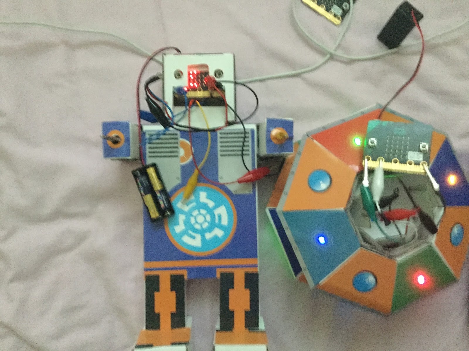
In part one of this series of posts, the project to get Consumable Robotics UFO and Dimm robot was started but focussed on the UFO kit. The goal being for some action on Dimm to trigger a series of messages being passed between the two of them. In this post, the focus moves to Dimm and the setting up the actions leading to the messaging. Stage 1 Build Using the Micro:bits port 0 (as part of the Dimm robot) for the input from the light sensor, which is included in the kit (Red lead going to 3v and the black lead going to GND). Just to note the less light there is the higher the value on the sensor.
Stage 2 Code Micropython programmed through the Mu editor (see below)
If light levels are high then : scroll a message saying "calling UFO" send the code "dimm" via bluetooth. otherwise: scroll a message saying "I can't see" If it recieves "ufo" via bluetooth : display "Hello, UFO called me" Micropython code import radio from microbit import pin0, pin1, display, sleep radio.on() while True: incoming = radio.receive() if incoming == 'ufo': display.scroll("Hello, UFO called me", 75) if pin0.read_analog()<175: display.scroll("calling UFO") radio.send("dimm") else: display.scroll("I can't see") Stage 3 Testing Video below shows it in action including what happens when the light (in this case a torch) shines on the sensor connected to Dimm; a message is sent and picked up by the UFO kit (LEDs flash and the message saying "DIMM calling" scrolls across the UFO LED array - see UFO talks to robot - part one for more details). A message is sent back from the UFO kit and on Dimm's LED array the message "Hello, UFO called me"). If the light levels are too low then the message "I can't see" scrolls across Dimm's LED array.
As an aside, the Dimm robot still reminds me, a little, of a colourful, friendly, Ood from Dr Who with all the leads hanging out of the 'mouth' - think that is geeky I know.
All opinions in this blog are the Author's and should not in any way be seen as reflecting the views of any organisation the Author has any association with. Twitter @scottturneruon
In an earlier post I played with 4Tronix's CrumbleBot to make an edge follower robot (http://robotsandphysicalcomputing.blogspot.co.uk/2015/07/edge-following-crumblebot.html). I wanted to play a little more, so I looked at making it 'explore' a room a bit and recently 4Tronix's have released an add-on panning ultrasonic sensor for the CrumbleBot - how can I resist?
What is a CrumbleBot The CrumbleBot (http://4tronix.co.uk/store/index.php?rt=product/product&product_id=493) is based around the Redfern Electronic's Crumble Controller (http://redfernelectronics.co.uk/crumble/) and Crumble software (http://redfernelectronics.co.uk/crumble-software/); providing an intuitive graphical interface (similar to Scratch) to control two motors and four inputs/outputs. The CrumbleBot comes with a number sensors including line-detecting sensors and Light-Dependent Resistors for light detection and you use crocodile clips to connect the sensors to the inputs/outputs. In essence, this is nice little framework for simple robotics and quite forgiving; the commands are kept to a minimum and loading the program to the bot is just one action. One suggestion, is to make sure you order the Crumble Controller at the same time as CrumbleBot, it is easy to forget if you haven't already got a crumble controller already. Building the 'Bot' is relatively simple and 4Tronix have provided some easy to follow instructions on-line (http://4tronix.co.uk/crumble/CrumbleBot.pdf) that are almost foolproof (I manage to build it!). Panning sensor This is an add-on piece (http://4tronix.co.uk/store/index.php?rt=product/product&keyword=crumblebot&category_id=0&product_id=556), at the time of writing this costing around £12 (with VAT), which adds a ultrasonic sensor that pans and is controlled using Crumble. The instructions for setting this up are available at http://4tronix.co.uk/blog/?p=1353 you need to read from about half way down the page, they are detailed and please don't do what I did and skim through them, missing out an important action. 'Explorerbot' The Crumblebot is built, the Panning ultrasonic sensor is connected - in my case IO port A for the servo to pan the sensor and IO port D for the input from the sensor - time to program it. The instructions in the set-up http://4tronix.co.uk/blog/?p=1353 include a useful little starting routine to read the sensor and 'zero' the sensor's position. So my exploring routine is based around
panning the sensor by +/-20 degrees of the sensor facing forward.
if an object is 5cm or less from the sensor; reverse the Crumblebot and make a slight turn; otherwise move forward.
The code is shown below:
The video shows the 'Explorerbot' in action.
Conclusion
It is good fun; this is a relatively simple problem but still fun. The Crumble language is Scratch-like and simple to set up and use. Crumble as a system I have, so far, found quite forgiving and this is useful - less fear of making a mistake.The panning sensor gives this already cute robot an even cuter look. Please feel free to add the discussion using the comment section.
All opinions in this blog are the Author's and should not in any way be seen as reflecting the views of any organisation the Author has any association with. Twitter @scottturneruon
For this project, it is a moving ‘bot’ made from waste materials, combined with an electric motor and a programmable device (in this case a Micro:Bit) to control (or try) it. An example is shown below. More details on junkbots can be found at http://junkbots.blogspot.co.uk/
Stage 1 - The start of a Junkbot
This stage is relatively simple. Tape some pens or straws to a drinks can.
The overall arrangement is show below, including a broken propellor as an unbalanced load to make the motor vibrate - the propellor was to hand but if you can secure something a clothes peg this could be used.
Stage 3 - Built Junkbot Now we just need to put them together by taping (or fixing somehow) the motor to the junkbot built in stage 1. A further possibility is to attach the Micro:Bit, motor driver board and battery pack to the junkbots; but this adds weight.
Stage 4 Code Using Micropython via the online editor https://www.microbit.co.uk to program the board and therefore the junkbot.
An example piece of code is shown below:
from microbit import *
def startIt():
pin8.write_digital(1)
pin12.write_digital(0)
pin0.write_digital(1)
pin16.write_digital(0)
def leftTurn(duration):
pin8.write_digital(0)
pin12.write_digital(1)
sleep(duration)
def stopIt():
pin8.write_digital(1)
pin12.write_digital(1)
sleep(2000)
while True:
startIt()
if button_a.is_pressed():
leftTurn(100)
if button_b.is_pressed():
stopIt()
Unplug the Micro:bit from the motor driver board and download the code to the microbit. Unplug the download cable and plug the Micro:Bit back into the motorboard, with the battery pack attached there is enough power for the Micro:Bit and the motor - don't plug in any other power including the programming cable when it is in the motor driver board.
All opinions in this blog are the Author's and should not in any way be seen as reflecting the views of any organisation the Author has any association with.
 I was only able to stay at Pi Wars for a short while on Saturday 1st April. Even so, as a spectator, it was good fun. Here are a few pictures (and a video) for the day.