Sunday 21 February 2021

Escape the Maze with a VR robot - Vex VR


You don't need to buy a robot to get programming a robot, now there are a range of free and relatively simple to start with robot simulators to play with. Three examples are listed below:

It is the last one of these (https://www.vexrobotics.com/vexcode-vr) that is the focus of this post and return to hit, after an earlier discussion in https://robotsandphysicalcomputing.blogspot.com/2020/04/programming-robots-virtually-1-vexcode.html 

Two of the nice things about the package, apart from being free, are it uses a Scratch-like programming language and it provides a 3D environment and models - playgrounds for a number of scenarios. 

So in this post, I will be discussing playing, or rather starting to play with the robot navigating a 3D maze (see the figure above). A feature I particularly like is you can change the views from an overhead view to an onboard version or one that seems to follow the robot.


So as I starting point I programmed it to essentially bounce along the walls keeping the wall on it's right and stopping when the downward 'eye' detects red on the floor for the end of the maze. The sensors include left and right bumper sensors; along with two sensors for detecting colours one facing forward and one down. The code I use is shown below:


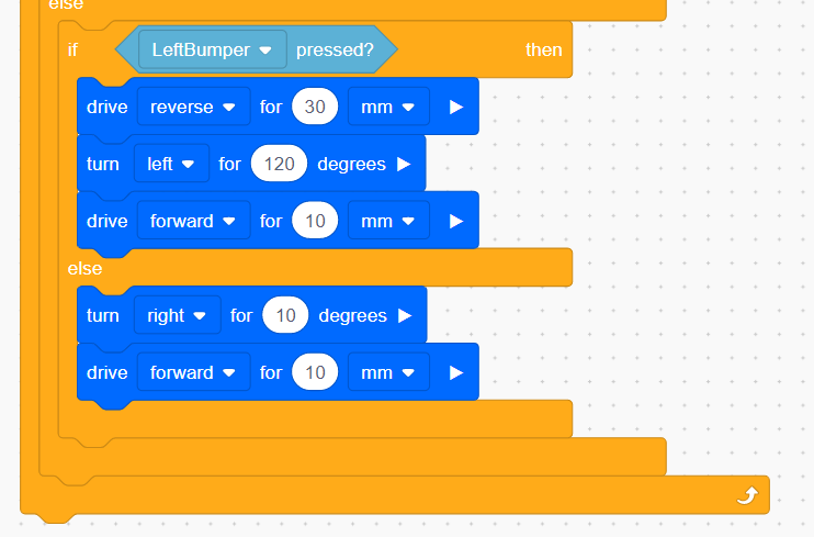
It took 8 minutes to solve the maze - which is slow. I would be interested to see the solutions of others being shared. As a simulated robot programming system this is great fun and challenging, I would recommend having a play iot is free and available at https://www.vexrobotics.com/vexcode-vr. I want to have a go with the Python version to replicate or better the solution above (start it as a text project rather than a blocks project when starting a new project).


All opinions in this blog are the Author's and should not in any way be seen as reflecting the views of any organisation the Author has any association with. Twitter @scottturneruon

Sunday 14 February 2021

Explaining the Tinkercad microbit Neural network

In a previous post, I looked at developing a neural network in Tinkercad around the Microbit (details available here) and the whole model can be found at  https://www.tinkercad.com/things/hPV4nU0Asr5-smooth-bojo 


Quick overview of a simple neural network; at its simplest is has at least three layers of neurons where the output of the first layer's neuron, the input layer, is connected as an input to every neuron in the next layer, the hidden layer. The output of the neurons in the hidden layer connects as inputs to every neuron in the final output layer - which gives the outputs from the network The figure below gives an overview; neurons are processing units.


Well, sort of. Neurons as processing units is certainly true for the hidden and the output layers. It is not true though for the input layer; this is literally a layer of inputs with no processing going on. So going back to the first figure of tinkercad microbit neural network and comparing it with the overview of the neural network we can see the three layers.


The input layer is just the two switches.  Hidden layer neurons taks the inputs and processes them (the red abd green microbits in the image. finally, the yellow microbit takes inputs from the 'hidden layer neurons' is the output layer - a single output requires a single neuron in the output layer.


Have a play,


All opinions in this blog are the Author's and should not in any way be seen as reflecting the views of any organisation the Author has any association with. Twitter @scottturneruon's 

Saturday 6 February 2021

Making a neural network in Tinkercad from Microbits

Tinkercad and microbit neural network

In a previous post I produced a single neuron based around microbits in Tickercad - see here.

To extend this the basic ideas discussed in that the previous post where extended to three microbit joined together. In  other words a network of neurones or neural network.

Basic requirements of a neuron are
Requirements 
- By altering the bias (or w0 in the example), weights change the behaviour of switches changes.
-when switch is pressed a variable x1 or x2 is set to 1 depending on which button is pressed and when released it goes to 0. 
- if (bias+w1*x1+w2*x2)>=0 then a T for True appears of the LEDs otherwise F for False is shown.

So by selecting the weights and connecting the outputs (p2) from the microbits labelled as Red and Green in the image above as inputs to the yellow microbit 'neuron' we can form a neural network. Switches as the inputs and the screen on the yellow 'neuron' as the output of the network showing true (T) or false(F).

So to build a XOR from the 'neurons'
'hidden layer'
Red microbit had the variables w0 set to -1 and W1 set to 0 and W2 set 1
Green microbit had the variables w0 set to -1 and W1 set to 1 and W2 set 0

'output layer'
Yellow microbit had the variables w0 set to -1 and W1 set to 1 and W2 set 1

All of this can be found at https://www.tinkercad.com/things/hPV4nU0Asr5-smooth-bojo or through the link shown below:


All opinions in this blog are the Author's and should not in any way be seen as reflecting the views of any organisation the Author has any association with. Twitter @scottturneruon

Saturday 30 January 2021

Blog stats: Most read posts in January 2021

Popular Posts


All opinions in this blog are the Author's and should not in any way be seen as reflecting the views of any organisation the Author has any association with. Twitter @scottturneruon

Thursday 21 January 2021

Tinkercad and Microbit: To make a neuron

The free online CAD (and so much more) package Tinkercad https://www.tinkercad.com/ under circuits; now has microbits as part of the list of basic components available to build circuits out of.

To have a quick play I wonder if using the built in Scratch=like code blocks, I could build a simulation of neuron on the microbit.

Requirements 
- By altering the bias, weights change the behaviour of buttons A and B
-when A is pressed a variable input1 is set to 1 and when released it goes to 0. The same happens for Button B and a variable input 2
- if (bias+weight1*input1+weight2*input2)>=0 then a T for True appears of the LEDs otherwise F for False is shown.

That is it really, apart initialising the variables. The code for producing an OR is shown below and the GIF at the end shows an AND in action:


The GIF below shows it action for an AND (bias is set to -2); change the bias to -1 and you would get an OR.


All opinions in this blog are the Author's and should not in any way be seen as reflecting the views of any organisation the Author has any association with. Twitter @scottturneruon

Saturday 2 January 2021

Playing with Marty the Robot: Set-up and go


This post forms part of occasional posts about playing  with Marty the Robot V2 (https://shop.robotical.io/products/marty-the-robot-v2) from Robotical. In this post I am going to do a quick look at initially setting it up and a bit of Scratch programming.


Set-up

I had a partially assembled version so most of the fiddly bits of putting the legs together etc were done; the instructions clearly make out the start of the instructions for building the partly assembled Marty. It is ready to build from the box including adding in a screwdriver. The only deviation I had to make from the build instructions was I having to partially disassemble the arm bit already done to fix the rest of the arm together - this was minor.


I am initially running this through an iphone and setting it up to do this was exceptionally easy to do and follow. 
  1. Download the app (just search for 'Marty the Robot' and found the right app), 
  2. pair it up with BlueTooth, 
  3. calibrate - just followed the instructions and it was fine.


Programming in Scratch

From the App there is an option to program in Scratch, just started it up and in the motion and sensing options there are blocks for Marty. Then it was just the same as other Scratch programming - an example is shown below.


Where next
Python, connecting to wifi and add some extras.


All opinions in this blog are the Author's and should not in any way be seen as reflecting the views of any organisation the Author has any association with. Twitter @scottturneruon

Friday 1 January 2021

Most viewed posts in December 2020 on the Robots and Physical Computing Blog

Popular Posts


All opinions in this blog are the Author's and should not in any way be seen as reflecting the views of any organisation the Author has any association with. Twitter @scottturneruon

Top posts on this blog in March 2024

The Top 10 viewed post on this blog in March 2024. Covering areas such as small robots, augmented reality, Scratch programming, robots. Micr...