Saturday, 6 February 2021

Making a neural network in Tinkercad from Microbits

Tinkercad and microbit neural network

In a previous post I produced a single neuron based around microbits in Tickercad - see here.

To extend this the basic ideas discussed in that the previous post where extended to three microbit joined together. In  other words a network of neurones or neural network.

Basic requirements of a neuron are
Requirements 
- By altering the bias (or w0 in the example), weights change the behaviour of switches changes.
-when switch is pressed a variable x1 or x2 is set to 1 depending on which button is pressed and when released it goes to 0. 
- if (bias+w1*x1+w2*x2)>=0 then a T for True appears of the LEDs otherwise F for False is shown.

So by selecting the weights and connecting the outputs (p2) from the microbits labelled as Red and Green in the image above as inputs to the yellow microbit 'neuron' we can form a neural network. Switches as the inputs and the screen on the yellow 'neuron' as the output of the network showing true (T) or false(F).

So to build a XOR from the 'neurons'
'hidden layer'
Red microbit had the variables w0 set to -1 and W1 set to 0 and W2 set 1
Green microbit had the variables w0 set to -1 and W1 set to 1 and W2 set 0

'output layer'
Yellow microbit had the variables w0 set to -1 and W1 set to 1 and W2 set 1

All of this can be found at https://www.tinkercad.com/things/hPV4nU0Asr5-smooth-bojo or through the link shown below:


All opinions in this blog are the Author's and should not in any way be seen as reflecting the views of any organisation the Author has any association with. Twitter @scottturneruon

Saturday, 30 January 2021

Blog stats: Most read posts in January 2021

Popular Posts


All opinions in this blog are the Author's and should not in any way be seen as reflecting the views of any organisation the Author has any association with. Twitter @scottturneruon

Thursday, 21 January 2021

Tinkercad and Microbit: To make a neuron

The free online CAD (and so much more) package Tinkercad https://www.tinkercad.com/ under circuits; now has microbits as part of the list of basic components available to build circuits out of.

To have a quick play I wonder if using the built in Scratch=like code blocks, I could build a simulation of neuron on the microbit.

Requirements 
- By altering the bias, weights change the behaviour of buttons A and B
-when A is pressed a variable input1 is set to 1 and when released it goes to 0. The same happens for Button B and a variable input 2
- if (bias+weight1*input1+weight2*input2)>=0 then a T for True appears of the LEDs otherwise F for False is shown.

That is it really, apart initialising the variables. The code for producing an OR is shown below and the GIF at the end shows an AND in action:


The GIF below shows it action for an AND (bias is set to -2); change the bias to -1 and you would get an OR.


All opinions in this blog are the Author's and should not in any way be seen as reflecting the views of any organisation the Author has any association with. Twitter @scottturneruon

Saturday, 2 January 2021

Playing with Marty the Robot: Set-up and go


This post forms part of occasional posts about playing  with Marty the Robot V2 (https://shop.robotical.io/products/marty-the-robot-v2) from Robotical. In this post I am going to do a quick look at initially setting it up and a bit of Scratch programming.


Set-up

I had a partially assembled version so most of the fiddly bits of putting the legs together etc were done; the instructions clearly make out the start of the instructions for building the partly assembled Marty. It is ready to build from the box including adding in a screwdriver. The only deviation I had to make from the build instructions was I having to partially disassemble the arm bit already done to fix the rest of the arm together - this was minor.


I am initially running this through an iphone and setting it up to do this was exceptionally easy to do and follow. 
  1. Download the app (just search for 'Marty the Robot' and found the right app), 
  2. pair it up with BlueTooth, 
  3. calibrate - just followed the instructions and it was fine.


Programming in Scratch

From the App there is an option to program in Scratch, just started it up and in the motion and sensing options there are blocks for Marty. Then it was just the same as other Scratch programming - an example is shown below.


Where next
Python, connecting to wifi and add some extras.


All opinions in this blog are the Author's and should not in any way be seen as reflecting the views of any organisation the Author has any association with. Twitter @scottturneruon

Friday, 1 January 2021

Most viewed posts in December 2020 on the Robots and Physical Computing Blog

Popular Posts


All opinions in this blog are the Author's and should not in any way be seen as reflecting the views of any organisation the Author has any association with. Twitter @scottturneruon

Wednesday, 23 December 2020

10 top read posts on Robots and Physical Computing blog in 2020

microbit and neopixel cube reacting to music


Please click on the links below for more details.

Popular Posts


All opinions in this blog are the Author's and should not in any way be seen as reflecting the views of any organisation the Author has any association with. Twitter @scottturneruon

Friday, 11 December 2020

Cube and microbit reacting to music


In a previous post - 'Dancing' Snowman - ok flashing LEDs to music - I played with Microbit V2 with its built-in microphone in combination with a Ryan Walmsley's SnowPi RGB https://www.kickstarter.com/projects/ryanwalmsley/snowpi-rgb-edition to make a Snowman that reacts to music.

In this post, the aim is to show the idea been extended to a Cube of programmable LEDs the 4tronix's Cube:Bit. Essentially the process is the same as the previous post the microphone detects the sound level and cause an LED to light up. 

Only a few minor changes were made to the code from the previous example.
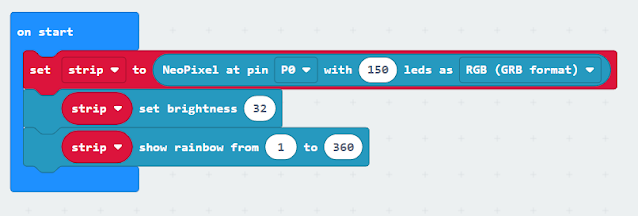
- The Pin had to be changed from 2 to 0 in the code (see Figure 1);
- Increase the number of pixels/LEDs in the settings (see Figure 1);
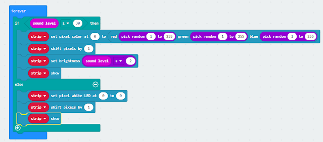
- It no longer chooses random LEDs/pixels to light up; but alters the first one and shifts the result to the result to the next one - so the lights shifts through the LEDs (see figure 2);
- Add in when it is quiet set the first LED to set a value and shift along (see figure 2)


Figure 1.


Figure 2


The code used is available at https://makecode.microbit.org/_3pT6zaRgy8T5 please feel to play and adapted and share your improvements.


The video below shows it in action:


All opinions in this blog are the Author's and should not in any way be seen as reflecting the views of any organisation the Author has any association with. Twitter @scottturneruon

Who wants to produce AI produced cartoon strips

Question: How easy is it produce a comic/cartoon using genetative AI? Let's start with  using ChatGPT4o to produce cartoons. The idea wa...