Just a short post today on getting the Micro:bit to sing using micropython. The process is covered very well in the Micro:bit-Micropython documentation. This post is just my notes really of what I did. The goal was to the try and replicate a bit of the intro to Kraftwerk's The Man-Machine (the repeating of Machine)- I came nowhere near it but it was fun trying.
Everything needs to be spelt out in Phonemes, which is a bit of a challenge, but I only had one word to do so that was ok. The Micro:bit-Micropython documentation has a list of the Phonemes allowed, you do need to get them right this was the most common error I found with the code. Pins 0 and 1 had croc-clips connecting them to the first and third parts on a speakers 3.5mm plug (as above) - thank you to Sway Grantham for showing me that.
from microbit import * import speech while True: speech.sing("MEYSHEYN ", pitch=90,speed=100) speech.sing("MEYSHEYN ", pitch=70, speed=80) speech.sing("MEYSHEYN ", pitch=60,speed=60)
It is good fun, but develop it away from others, it has the potential to annoy.
It also works with 4Tronix's (thank you for the suggestion) Micro:Bit PlayGround - only one connection needed this time.
All opinions in this blog are the Author's and should not in any way be seen as reflecting the views of any organisation the Author has any association with. Twitter @scottturneruon
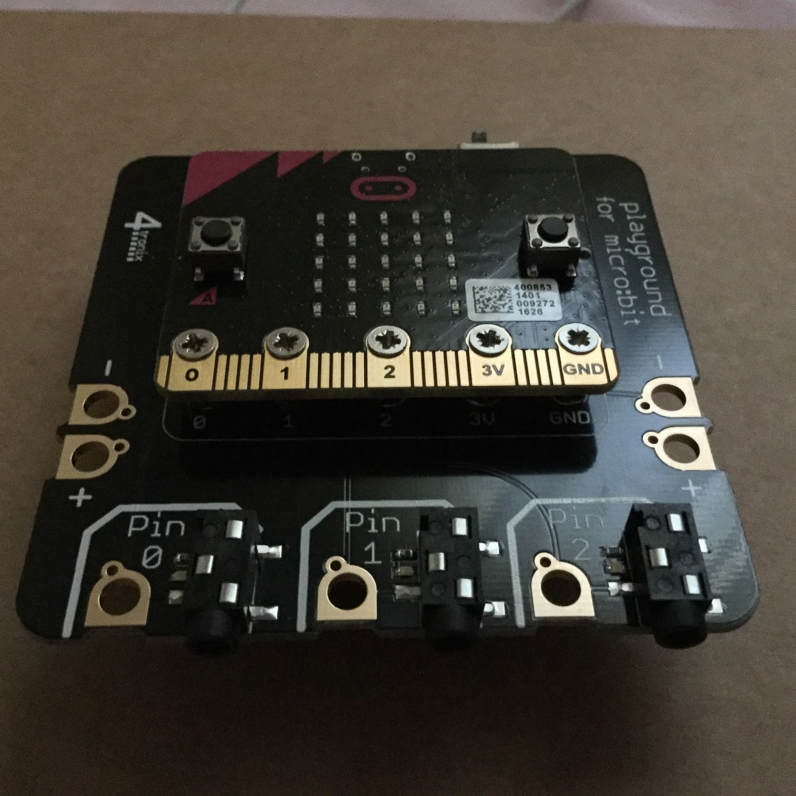
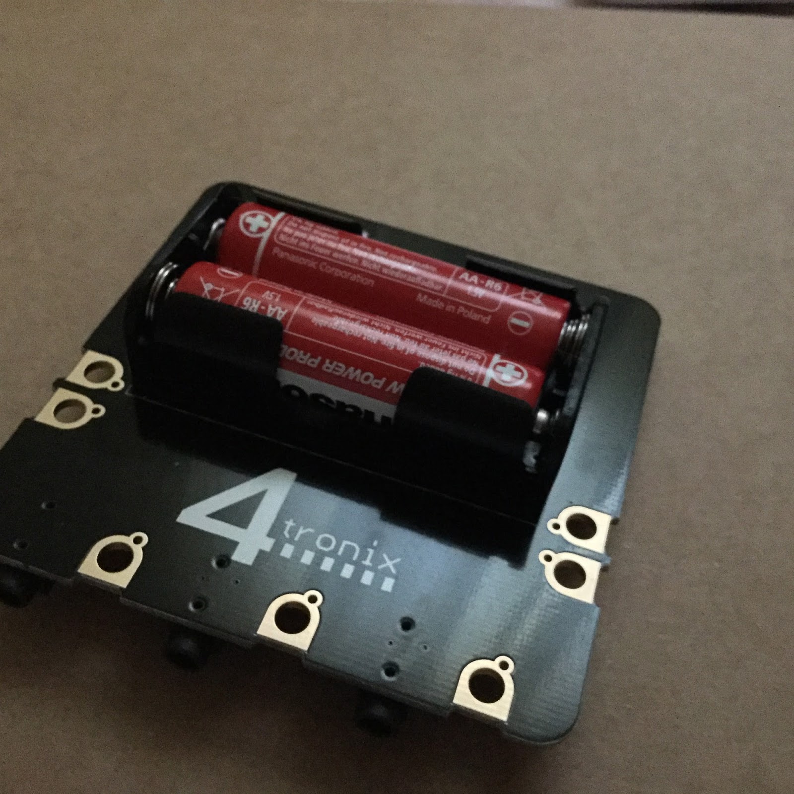
As much as I like the simplicity and flexibility of Crocodile Clips connecting components to a Micro:Bit, it can get a bit of a rat's nest of wires (especially if you are as messy as I am!). 4Tronix's have released their Micro:Bit PlayGround (http://4tronix.co.uk/store/index.php?rt=product/product&path=89&product_id=580)which is a board that has 3.5mm jack plugs to connect to a range of Gizmos (their phrase not mine) to which the Micro:Bit is screwed into. The battery pack is integrated onto the board on its back (see image below)
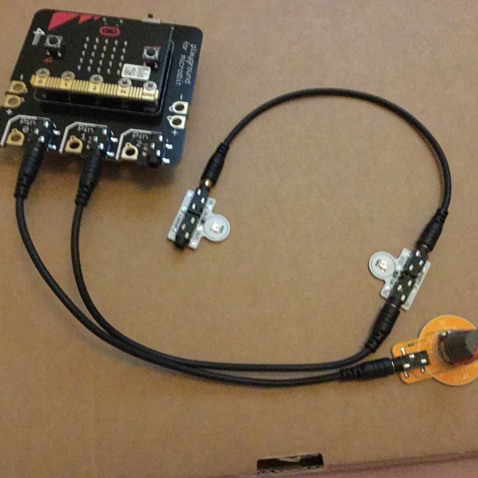
The Micro:Bit screws into the PlayGround via five screws which also for the connection between the PlayGround and the 'bit'. Below via the three cables connecting 3.5mm plugs, I have attached a 'Dial' (a potentiometer ) and two Flames (neopixels) to change the LED/neopixel's colours by rotating the Dial. Pin 0 has the 'Dial' attached and Pin 1 has the two Flames (neopixels) attached the out from the first goes in as input of the second via one the cables.
Code Essentially vary the 'Dial' varies the R,G,B values going to the two Flames/neopixels and so varying their colours. The code used is shown below. from microbit import * import neopixel # Setup the Neopixel strip on pin0 with a length of 2 pixels np = neopixel.NeoPixel(pin1, 2) while True: s1=int(pin0.read_analog()/5) np[0] = (255, s1, 255-s1) np[1] = (s1,255, 255-s1) np.show() Video of it in action Thoughts I like the idea that the cable doing both the power and control for the Gizmos, it does simplify building a little, more importantly it does produce less clutter (not so many wires). The whole unit with the batteries installed is a little weighty but that does give it at the same a sense of sturdiness which is a positive feature for just playing around - you wouldn't use it for wearables. Not using croc clips also avoids issues with the clips slipping off with rough handling. Nice little arrangement which I am enjoying playing - is for everyone? Probably not, but does provide a sturdy system to experiment with some standardised units. Related Links Micro:Bit Playground - Starter Kit Traffic lights - Microbit, GlowBugs and micropython
All opinions in this blog are the Author's and should not in any way be seen as reflecting the views of any organisation the Author has any association with. Twitter @scottturneruon
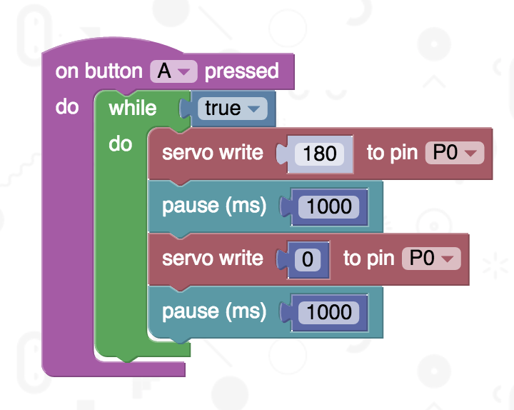
You can control servos (small ones) from a Micro:Bit directly. Following a link from the David Whale (Twitter @whaleygeek) , thank you, took me to a Kitronik blog post, https://www.kitronik.co.uk/blog/using-bbc-microbit-control-servo/, which has the answer. The code uses Microsoft Blocks taken from the post, runs the servos 180 degrees and back again, when button A is pressed. It does exactly what it should. I am also using the Tower Pro SG90 servo.
Can it be replicated in Micropython? This is a new mini project, there seems to be little out there yet on how do this but the best so far is this video by PHILG2864: The closest I have is the following, it is essentially there. from microbit import * pin0.set_analog_period(20) while True: pin0.write_analog(180) sleep(1000) pin0.write_analog(1) sleep(1000) Setting the time period to 20ms pin0.set_analog_period(20)seems by experiment (and used in the video above) to be best value so far. The reason for pin0.write_analog(1) set to 1 instead of 0, 0 seems to stop the whole thing.
All opinions in this blog are the Author's and should not in any way be seen as reflecting the views of any organisation the Author has any association with. Twitter @scottturneruon
In previous posts (UFO has Landed and DIMM the OOD), I started playing with the CBiSEducation's UFO consumable robots. Still using the Micro:Bit, in this two part post series, I am going to be playing with using Micropython to send messages between the two kits.
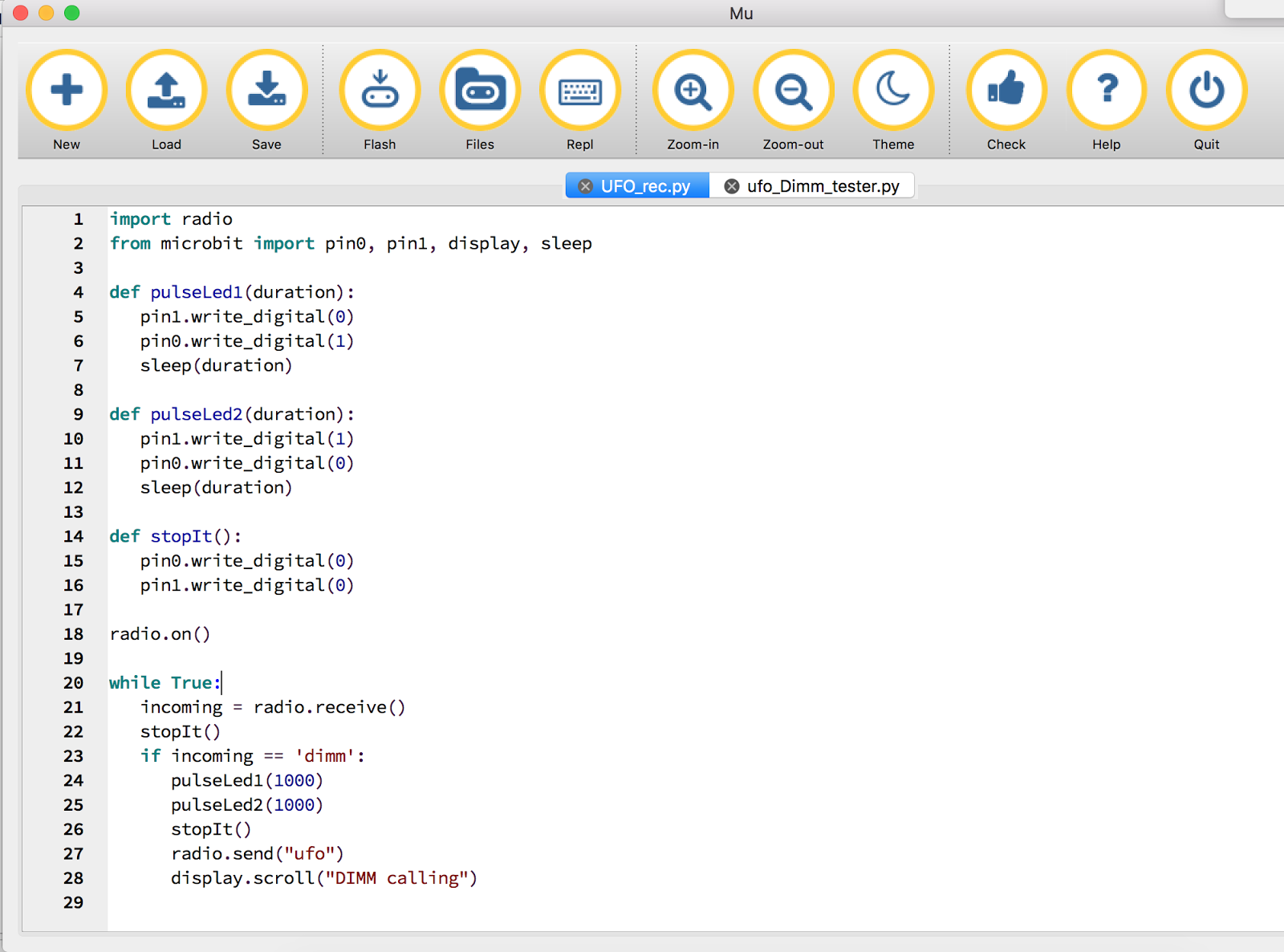
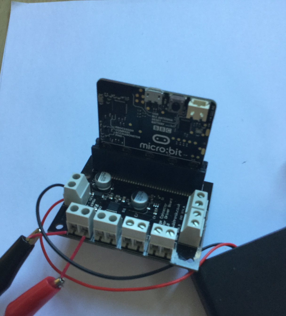
Stage 1 Wiring and Set up-UFO Pins 0 and 1 are outputs to the LEDs The black leads on the UFO go to GND. Micropython, using the Micro:Bit's built in radio module (Bluetooth), is used to communication between the two kits. Stage 2 Code -UFO The code is set to flash the UFO's LEDs and then scroll a message "DIMM Calling" when it receives a message "dimm" via Bluetooth. Basic overview is - Turn on the radio module - radio.on() - If the message is received then turn the LEDs on and off and scrolls "DIMM calling" across the LED array. - send a message via bluetooth "ufo" to whoever is listening (in the end the robot DIMM hopefully). The code is shown below. import radio from microbit import pin0, pin1, display, sleep def pulseLed1(duration): pin1.write_digital(0) pin0.write_digital(1) sleep(duration) def pulseLed2(duration): pin1.write_digital(1) pin0.write_digital(0) sleep(duration) def stopIt(): pin0.write_digital(0) pin1.write_digital(0) radio.on() while True: incoming = radio.receive() stopIt() if incoming == 'dimm': pulseLed1(1000) pulseLed2(1000) stopIt() radio.send("ufo") display.scroll("DIMM calling") To use the radio module you will need to switch to the mu editor (http://codewith.mu/).
Stage 3 Testing it To test it, a second Micro:bit was used to send test signals (the code for this is shown below). When button A is pressed on the second Micro:Bit a message 'dimm' is sent followed by sending 'not'. import radio from microbit import button_a, button_b, sleep radio.on() while True: if button_a.is_pressed(): radio.send('dimm') radio.send('not') if button_b.is_pressed(): radio.send('ufo') radio.send('not')
The UFO does cycle through the sequence LEDs flash and the message scrolls. The slight bug is in repeats it several times before it stops; possibly a buffering issue somewhere. Stage 4 In the next post (http://bit.ly/2d3zlh0), I will be building the Robot DIMM part of the system - sending and receiving message and detecting light levels in micropython.
All opinions in this blog are the Author's and should not in any way be seen as reflecting the views of any organisation the Author has any association with. Twitter @scottturneruon
In an earlier post, I showed how you could build a Micro:Bit controlled Junkbot. In this post I want to show a modification to it, to use one Micro:Bit to control the junkbot controlled by another Micro:Bit. A nice feature of the Micro:Bit using micropython, is it can send and receive simple messages via radio - so here is my take on it. The first problem is the Python editor available on https://www.microbit.co.uk/ does not seem to work with the radio API. One solution to this is to change to the mu editor.
Two pieces of code are needed. Sending Code for the 'remote' control: Essentially it is set up to send two messages, via the built-in radio module, spinl or spinr depending on which button is pressed. import radio from microbit import button_a, button_b radio.on() while True: if button_a.is_pressed(): radio.send('spinl') if button_b.is_pressed():
radio.send('spinr') Junkbot Code This takes an adapted form of the previous Junkbot code to work by; on receiving spinl or spinr via the radio link; spin the motor clockwise or anticlockwise. import radio from microbit import pin8, pin12, sleep def leftTurn(duration): pin8.write_digital(0) pin12.write_digital(1) sleep(duration) def rightTurn(duration): pin8.write_digital(1) pin12.write_digital(0) sleep(duration) def stopIt(): pin8.write_digital(0) pin12.write_digital(0) radio.on() while True: incoming = radio.receive() if incoming == 'spinl': leftTurn(500) stopIt() if incoming == 'spinr': rightTurn(500) stopIt()
All opinions in this blog are the Author's and should not in any way be seen as reflecting the views of any organisation the Author has any association with.
For this project, it is a moving ‘bot’ made from waste materials, combined with an electric motor and a programmable device (in this case a Micro:Bit) to control (or try) it. An example is shown below. More details on junkbots can be found at http://junkbots.blogspot.co.uk/
Stage 1 - The start of a Junkbot
This stage is relatively simple. Tape some pens or straws to a drinks can.
The overall arrangement is show below, including a broken propellor as an unbalanced load to make the motor vibrate - the propellor was to hand but if you can secure something a clothes peg this could be used.
Stage 3 - Built Junkbot Now we just need to put them together by taping (or fixing somehow) the motor to the junkbot built in stage 1. A further possibility is to attach the Micro:Bit, motor driver board and battery pack to the junkbots; but this adds weight.
Stage 4 Code Using Micropython via the online editor https://www.microbit.co.uk to program the board and therefore the junkbot.
An example piece of code is shown below:
from microbit import *
def startIt():
pin8.write_digital(1)
pin12.write_digital(0)
pin0.write_digital(1)
pin16.write_digital(0)
def leftTurn(duration):
pin8.write_digital(0)
pin12.write_digital(1)
sleep(duration)
def stopIt():
pin8.write_digital(1)
pin12.write_digital(1)
sleep(2000)
while True:
startIt()
if button_a.is_pressed():
leftTurn(100)
if button_b.is_pressed():
stopIt()
Unplug the Micro:bit from the motor driver board and download the code to the microbit. Unplug the download cable and plug the Micro:Bit back into the motorboard, with the battery pack attached there is enough power for the Micro:Bit and the motor - don't plug in any other power including the programming cable when it is in the motor driver board.
All opinions in this blog are the Author's and should not in any way be seen as reflecting the views of any organisation the Author has any association with.
Matthew Hole, a student from Wrenn Academy, Northamptonshire ; has been investigating this idea whilst on a Nuffield Research Placement (http://www.nuffieldfoundation.org/nuffield-research-placements) working with Dr Scott Turner, University of Northampton. The project was to look into developing junkbots controlled using a Micro:bit and also to produce some materials for schools to use with or without outside assistance.
What is a Junkbot?
For this project, it is a moving ‘bot’ made from waste materials, combined with an electric motor and a programmable device (in this case a Micro:Bit) to control (or try) it. An example is shown above. More details on junkbots can be found at http://junkbots.blogspot.co.uk/
All opinions in this blog are the Author's and should not in any way be seen as reflecting the views of any organisation the Author has any association with.
It is simple, timings and more lights can be added to make a more interesting system. If you have done something similar please use the comments to discuss or link to it. Thank you to @SCC_Lancaster for the loan of a micro:bit. Related Posts Microbit and GlowBugs CodeBug and Glowbugs
All opinions in this blog are the Author's and should not in any way be seen as reflecting the views of any organisation the Author has any association with.